
Wire Assembly vs. Cable Assembly: What’s the Difference?
Wire assemblies and cable assemblies are used to transmit power, signals, and data between components, equipment, and electronic systems.
The terms are sometimes used interchangeably, and terminology can vary between industries and customer drawings. In practice, the distinction often comes down to conductor construction, protection, routing, mechanical requirements, and the intended application.
Understanding these differences can help OEM engineers and buyers communicate product requirements more clearly when preparing drawings, BOMs, and RFQs.
What Is a Wire Assembly?
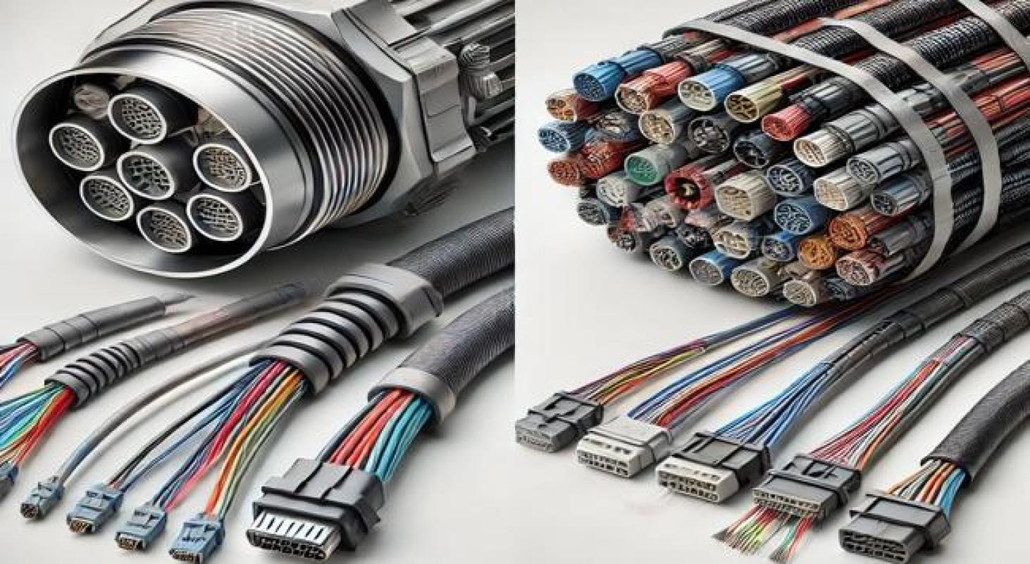
A wire assembly generally consists of one or more individual insulated wires that are cut, stripped, terminated, and assembled according to a customer-defined configuration.
Depending on the design, a wire assembly may include:
-
Individual insulated wires
-
Crimped terminals or contacts
-
Connectors
-
Soldered terminations
-
Splices
-
Heat-shrink
-
Labels or identification
-
Protective sleeving
-
Customer-defined routing or bundling
Wire assemblies are often used for relatively direct electrical connections between components, switches, sensors, boards, power sources, or other devices.
The exact configuration should be defined by the approved drawing, BOM, pinout, and applicable manufacturing documentation.
What Is a Cable Assembly?
A cable assembly uses a cable or group of conductors that is terminated with connectors, contacts, terminals, or other components to create a finished electrical interconnect.
Depending on the application, a cable assembly may use:
-
Multi-conductor cable
-
Shielded cable
-
Coaxial cable
-
Twisted-pair cable
-
Flat or ribbon cable
-
Power cable
-
Data or communication cable
-
Customer-specified wire and cable constructions
Additional components may include:
-
Connectors
-
Terminals or contacts
-
Overmolding
-
Strain relief
-
Shield termination
-
Protective sleeving
-
Heat-shrink
-
Labels
-
Grommets
-
Customer-defined protective materials
Cable assemblies may be designed for power, signal, data, control, RF, or other electrical requirements.
Learn more about: Custom Cable Assemblies
Wire Assembly vs. Cable Assembly
There is no single construction rule that applies to every product, but the following differences can help clarify how the terms are commonly used.
Conductor Configuration
Wire Assembly:
Often uses individual insulated wires or a small group of wires assembled for a defined connection.
Cable Assembly:
Often uses a manufactured cable construction or grouped conductors designed around specific electrical and mechanical requirements.
Protection
Wire Assembly:
May use basic insulation, sleeving, heat-shrink, loom, or other protective materials when required.
Cable Assembly:
May include an outer jacket, shielding, overmolding, strain relief, or other protection depending on the application.
Electrical Requirements
Wire Assembly:
Commonly used for power, control, sensor, or point-to-point electrical connections.
Cable Assembly:
May support power, signal, high-speed data, RF, communication, shielding, impedance, or other customer-defined requirements.
Mechanical Requirements
Both wire and cable assemblies may require specific:
-
Lengths and tolerances
-
Bend radius
-
Connector orientation
-
Cable exit direction
-
Strain relief
-
Flexibility
-
Routing
-
Environmental protection
These requirements should be defined by the individual product design rather than assumed from the product name alone.
Where Does a Wire Harness Fit?
A wire harness typically organizes multiple wires, branches, connectors, terminals, and protective materials into a defined routing configuration.
Wire harnesses are commonly used when an electrical system requires multiple connection points or branches within machinery, vehicles, industrial equipment, medical equipment, or other
OEM systems.
For a detailed comparison between cable assemblies and wire harnesses, read: Cable Assembly vs. Wire Harness: Key Differences
For manufacturing information: Wire Harness Assemblies
Common Wire & Cable Assembly Applications
Wire and cable assemblies are used across many types of OEM equipment.
Applications may include:
Industrial & Automation
-
Sensors
-
Motors
-
Actuators
-
Control equipment
-
Machinery
-
PLC and HMI systems
-
Robotics
Automotive
-
Lighting systems
-
Sensors
-
Control modules
-
Vehicle electronics
-
Infotainment systems
-
Equipment wiring
Medical & Healthcare Equipment
-
Diagnostic equipment
-
Monitoring systems
-
Medical electronics
-
Customer-specific device interconnections
Telecom & Communications
-
Networking equipment
-
Data connections
-
RF connections
-
Communication systems
Consumer Electronics
-
USB connections
-
Power connections
-
Data connections
-
Computer equipment
-
Customer-specific device interconnections
The construction of each assembly should be based on the electrical, mechanical, environmental, and manufacturing requirements of the individual application.
Key Design Information for an OEM Project
When requesting a custom wire or cable assembly, clearly defined documentation helps reduce manufacturing questions and quotation delays.
Useful information may include:
-
Drawing
-
Bill of Materials (BOM)
-
Wiring diagram or pinout
-
Connector manufacturer and part numbers
-
Terminal or contact part numbers
-
Wire or cable specifications
-
Cable lengths and tolerances
-
Electrical requirements
-
Shielding and grounding requirements
-
Mechanical requirements
-
Environmental requirements
-
Labels and identification
-
Prototype quantity
-
Production quantity
-
Estimated annual volume
-
Inspection requirements
-
Testing requirements
-
Current revision
-
Target delivery date
If some information is still under development, an engineering review can help identify additional information needed before manufacturing.
Learn more: Cable Assembly Engineering Support
How Wire & Cable Assemblies Are Manufactured
Manufacturing processes depend on the approved product design.
Typical processes may include:
-
Drawing and BOM review
-
Material and component verification
-
Wire or cable cutting
-
Stripping and preparation
-
Crimping or terminal installation
-
Soldering when required
-
Connector assembly
-
Shield preparation and termination when required
-
Sleeving, heat-shrink, or other protective finishing
-
Overmolding or strain relief when specified
-
Labeling and identification
-
Inspection and electrical testing
Inspection and testing should follow the approved product documentation and customer-defined requirements.
Y.C. Cable's in-house testing capabilities include continuity, Hi-Pot, and pull-force testing. Additional inspection or testing requirements may apply depending on the individual customer program.
Final application-level validation, including system compatibility and end-use testing, remains the customer's responsibility unless otherwise agreed as part of the project requirements.
Learn more: Cable Assembly Manufacturing Capabilities
Choosing the Right Assembly for Your Application
The correct solution should be determined by the requirements of the finished product rather than by terminology alone.
Important factors may include:
-
Number of electrical connections
-
Power, signal, data, or RF requirements
-
Cable routing
-
Space limitations
-
Flex or movement
-
Shielding
-
Environmental exposure
-
Connector requirements
-
Mechanical protection
-
Production quantity
-
Inspection and testing requirements
For OEM projects, the drawing, BOM, pinout, and product requirements should ultimately define what is manufactured.
Request a Custom Wire or Cable Assembly Quote
Y.C. Cable supports custom wire and cable assembly programs from prototype and NPI builds through repeat production.
For project review, send us your available drawings, BOM, pinout, connector requirements, quantities, inspection and testing requirements, and target schedule.