How Custom Robotic Cable Assemblies Improve Automation Systems
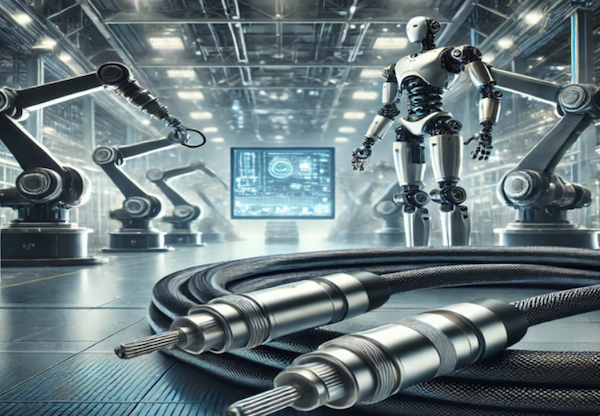
Robotic and automation systems can place very different mechanical demands on cable assemblies than stationary equipment.
A robotic cable design should therefore be based on the actual motion profile, routing path, electrical requirements, connector system, operating environment, and expected mechanical conditions of the application.
The following factors are important when defining a robotic cable assembly.
Define the Motion Profile
Begin by identifying how the cable will move.
Requirements may involve:
- Repeated bending
- Continuous flex
- Torsional movement
- Multi-axis motion
- Drag-chain travel
- Reciprocating movement
- Fixed routing with localized movement
A cable designed for one type of motion should not automatically be assumed suitable for another.
Bend Radius
Available bend radius can affect cable construction and routing.
Engineering information should identify:
- Minimum available bend space
- Repeated vs. static bending
- Cable diameter
- Routing path
- Nearby mechanical components
- Cable-entry direction
Routing the cable below an appropriate bend radius may increase mechanical stress on conductors, shielding, jackets, and connector transitions.
Torsion and Multi-Axis Movement
Robotic arms and other multi-axis equipment may twist cables as the system moves.
Important information can include:
- Direction of rotation
- Amount of torsion
- Repeated rotation
- Cable length
- Location of the twisting section
- Combined flex and torsion
These requirements should be defined during engineering review rather than assuming a generic “high-flex” cable will meet every robotic motion profile.
Drag-Chain Applications
Cables installed in drag chains may require review of:
- Travel distance
- Bend radius
- Cable diameter
- Chain dimensions
- Cable separation
- Movement speed
- Acceleration
- Installation orientation
- Other cables or hoses sharing the chain
The complete routing system should be considered when selecting the cable construction.
Electrical Requirements
Robotic cable assemblies may carry:
- Power
- Control signals
- Sensor signals
- Communication data
- Encoder signals
- Other customer-defined electrical circuits
Specify:
- Voltage
- Current
- Wire gauge
- Signal type
- Data requirements
- Pinout
- Connector system
Mechanical flexibility should not be evaluated separately from the electrical requirements.
Shielding and Grounding
Automation equipment may operate near motors, drives, power cables, and other potential electrical-noise sources.
Depending on the system design, requirements may include:
- Foil shielding
- Braided shielding
- Drain wires
- Shield termination
- Grounding
- Shielded connectors
- Twisted-pair construction
Shielding should be selected according to the actual electrical and EMI/RFI requirements.
Connector Retention and Cable Exit
Motion can also place stress on connector interfaces.
Consider:
- Connector orientation
- Cable exit direction
- Retention method
- Mating cycles
- Strain near the connector
- Available mounting space
- Service access
The cable routing should avoid transferring unnecessary mechanical load directly to the connector.
Strain Relief and Overmolding
Depending on the application, strain-relief features may help manage the cable-to-connector transition.
Options may include:
- Molded strain relief
- Overmolding
- Heat-shrink
- Protective sleeving
- Mechanical clamps
The appropriate method depends on connector geometry, cable construction, motion, material, and customer requirements.
For molded configurations, visit Overmolded Cable Assemblies.
Environmental Conditions
Robotic equipment may also be exposed to:
- Oil
- Dust
- Moisture
- Abrasion
- Temperature
- Vibration
- Industrial chemicals
These conditions should be identified before cable jacket, protection, and connector requirements are finalized.
Information to Provide for a Robotic Cable Project
Useful project information includes:
- Drawing
- BOM
- Motion profile
- Bend radius
- Torsion requirements
- Travel distance
- Connector information
- Cable specification
- Voltage and current
- Signal or data requirements
- Shielding requirements
- Environmental conditions
- Prototype quantity
- Testing requirements
From Robotic Cable Design to Manufacturing
Y.C. Cable manufactures robotic cable assemblies according to customer-approved drawings, BOMs, electrical requirements, motion requirements, connector specifications, and testing criteria.
For product configurations, visit Custom Robotic Cable Assemblies.
For broader engineering considerations, visit Robotics Cable Assembly Solutions.